Eaton Char-Lynn Motor – Car Motor: Which Black Technology?
Eaton Char-lynn Motor : “The car motor has been in development for a hundred years. What are the black technologies in the motor? Where are the best?”
There are not many diesel motors in contact, so it is mainly about gasoline motors.
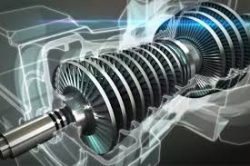
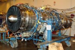
1. Turbocharging technology
In 1905, when Dr. Alfred Buchi applied for the patent for the first turbocharger (power-driven axial supercharger), it was estimated that he did not expect that what he brought to the field of automobile motors was such a big influence. Black technology.
Turbo technology, it has been more than 100 years old. By 1961, the car began to tentatively install the supercharger, but because of the tremendous pressure and heat generated in an instant, the effect after installation was not satisfactory. Saab, from Northern Europe, is the first car manufacturer to apply turbochargers to automotive products. The Saab 99 car, which was introduced in 1977, makes the car motor use turbo technology. It began to mature, and its arrival also announced the birth of a new era in the automotive industry. Turbo technology rewrites the traditional concept of “displacement size determines power.”
2, Atkinson cycle
The motor in the form of a conventional crank-link has four strokes of intake-compression-work-exhaust in one cycle. This cycle of motor was invented by Otto in 1876, and the cycle of this motor was Named the Otto loop.
The Atkinson cycle was invented in 1882 by British motorer James Atkinson. The Atkinson cycle motor increases efficiency but reduces power density, which has the disadvantage of low efficiency and poor torque at low speeds. The Atkinson cycle motor is currently used on some hybrid vehicles.
Atkinson’s core philosophy: To improve thermal efficiency (that is, to save fuel), it is necessary to make the power stroke longer than the compression stroke (that is, the distance that the piston is pushed back after ignition is greater than the distance of the piston compression mixture before ignition).
Since the introduction of the Atkinson Cycle (Miller Cycle) in 1940, there have been many manufacturers to develop it. In theory, it is not a black technology. Due to the dynamic characteristics of its motor, it has not been noticed in the early years, and with the development trend of new energy vehicles, it is now slowly being promoted by the major media manufacturers.
3. FSI in-cylinder stratified injection technology
This technique is based on a more detailed injection logic determination based on direct injection in the cylinder. In principle, the internal combustion of the motor requires air and fuel, and the ideal ratio of the two is 14.7:1. Considering that the mixture of the traditional motor is formed in the intake passage, the ratio of air to fuel is affected by the intake air flow. The influence of the valve switch is large, and the tiny fuel particles are adsorbed on the pipe wall, so the traditional multi-point EFI is difficult to approach the ratio of 14.7:1, while the direct injection supplies the fuel to the nozzle in the cylinder. The nozzle, and then the most appropriate time to control the fuel injection through the computer, has improved the technology compared to the traditional EFI, which is also the technology applied by many domestic motors.
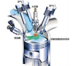
The FSI motor uses a high-pressure pump to pass fuel through a split rail to the electromagnetically controlled high-pressure injector. It is characterized in that a variable eddy current has been generated in the intake passage, so that the intake air flow forms an optimal vortex form into the combustion chamber, and is pushed in a layered manner, so that the mixed gas is concentrated around the spark plug located in the center of the combustion chamber, if the air The proportion of fuel is more than 25:1. It can’t be ignited according to the routine. Therefore, it is necessary to adopt a stratified combustion method from rich to lean. The movement of air in the cylinder forms a dense mixture which is easy to ignite around the spark plug, and the outer layer is gradually thin. After the rich mixture is ignited, the combustion quickly spreads to the outer layer, which not only can make the combustion in the cylinder more fully, but also improve the motor’s dynamic response and save fuel.
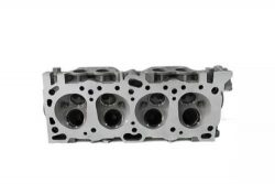
4, Audi AVS variable valve lift technology
VVT variable valve timing technology can be simply understood as the initial version of AVS. Now almost all motors use a four-valve configuration, which means that there are two intake and exhaust valves on each cylinder, and the time of opening through the valve. To constantly change the amount of air in the cylinder, when the motor is running at high speed, the opening and closing of the valve every tens of times is dozens of times. Therefore, if the time and the rule of opening the intake valve are fixed, it is easy to cause high working conditions. Insufficient intake air and too much intake air during idle speed. In order to alleviate this contradiction, motorers have developed VVT variable timing technology, which changes the opening and closing time of intake and exhaust valves under different working conditions. Since there is only one camshaft that cannot change the angle of the cam, how to adjust its adjustment range is also very limited.
The AVS variable valve lift technology solves the problem that VVT can’t solve: firstly, two sets of cams with different angles are designed for each intake valve, and a spiral grooved sleeve is installed on the camshaft, and the spiral groove sleeve is installed. The cylinder is controlled by an electromagnetic actuator to switch between two different sets of cams to change the lift of the intake valve, thus ensuring that the motor switches to a smaller cam at low load and low speed to achieve a shortened valve lift. Purpose; and switch to a larger cam when the motor is under high load and high speed. At this time, the cam stroke is longer and the corresponding intake time is longer.
5, Mazda compression ignition gasoline motor
Although Mercedes-Benz and GM have long used HCCI gasoline compression ignition technology, here I am talking about the Mazda SKYACTIV-X compression-ignition gasoline motor. SPCCI (Spark Controlled Compression Ignition) spark control compression ignition technology. Mazda’s SKYACTIV-X compression-ignition motor is capable of achieving ultra-thin combustion in an oil-gas mixture with a condition that the air is more than twice the theoretical air-fuel ratio, thereby improving thermal efficiency.
For ultra-thin gas mixtures, conventional spark plug ignition is difficult to achieve. Mazda uses spark plugs on the SKYACTIV-X compression-ignition motor to assist ignition. Studies have shown that the emitted electric spark will slowly appear flame and expand, like an expanding flame ball. By expanding the flame ball and then compressing the mixed gas with the up and down movement of the piston, the ultra-thin mixture can be stably self-ignited. The flame ball generated by this auxiliary ignition not only raises the temperature inside the cylinder, but also applies a new pressure to the cylinder, which is more conducive to the compression ignition of gasoline.
In addition, when the ignition ignition can not meet the operating conditions of the motor, the motor can also automatically switch to spark plug ignition. At this point, the mixture will become thicker and the motor will provide more power.
With the compression of the black technology of gasoline compression ignition, the compression ratio of the gasoline motor will be unprecedented 18:1 (the current compression ratio is Mazda’s SKYACTIV-G, the compression ratio is 14:1 – but this is not true motor compression ratio, but achieved by gas distribution technology). An increase in compression ratio means higher fuel efficiency and better power performance. And the thermal efficiency of the diesel motor for general use of compression ignition technology is above 40%, so we can also predict that the thermal efficiency of the SKYACTIV-X gasoline motor with the same ignition method can easily achieve more than 40%.
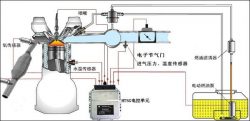
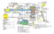
6. Intake manifold water injection system
This system comes from Bosch, and water jets are not Bosch’s original creations. This technology was used in bombers of various countries during World War II. Later in the motor sports, this is also a must-have equipment for many cars, so this project technology has long been a mature mechanism.
The biggest limitation of the turbocharged motor power output is the high temperature of the intake system. Excessive intake air temperature can easily cause motor knock and reduce power. Usually, in this case, when the temperature is too high, the motor will use more gasoline to evaporate and cool down. If you use oil to cool down, it is enough to be extravagant.
The water injection system injects water in a storage tank of the vehicle into the intake manifold in a high-pressure water mist manner, and the high-pressure water mist vaporizes and evaporates to bring some heat into the air in the gas manifold, and passes through the high pressure. The water cooled by the water mist will have a lower temperature and a higher density, thus outputting higher power.
At present, motor water spray technology has appeared on the BMW M4 GTS model.
7, particle trap
A particulate trap, produced for emissions and environmental protection, is a ceramic filter installed in the motor’s exhaust system that captures particulate matter before it enters the atmosphere. Among them, diesel particulate trap: DPF (Diesel Particulate Filter), gasoline particulate trap: GPF (Gasoline Particulate Filter).
motor pollution comes mainly from four components – particulate matter (PM), hydrocarbons (HCx), nitrogen oxides (NOx) and carbon monoxide (CO). Most of the particulate matter (soot) is composed of tiny particles of carbon or carbide (less than 4-20 μm in size).
The particle trap can reduce the amount of soot produced by the motor by more than 90%. The captured particulate matter is then burned out during vehicle operation. The basic principle of its work is: If the diesel particulate filter is sprayed with metal platinum, rhodium, palladium, the black smoke containing carbon particles emitted by the diesel motor enters the motor exhaust particulate trap through a special pipeline, and is densely arranged through the interior. The bag filter adsorbs the soot particles on the filter made of metal fiber felt; when the adsorption amount of the particles reaches a certain level, the burner at the tail end is automatically ignited and burned, and the soot particles adsorbed thereon are burned off. It becomes carbon dioxide that is harmless to the human body. To do this, the exhaust aftertreatment system uses advanced electronic control systems, catalytic coatings and fuel-added catalysts (FBC). This fuel additive type catalyst contains a metal such as ruthenium, iron, and platinum. These materials are added to the fuel in proportion, and with the help of the motor control system, not only the amount of particulate emissions, but also the emissions of pollutants such as hydrocarbons and pollutants are controlled. The regeneration or purification function of the trap must be done on a controlled basis to keep the trap from being clogged with soot. At the end of the purification cycle, any residual dust or filter residue will eventually be artificially removed during routine maintenance.
This black technology is more difficult to understand, and it is not to improve combustion efficiency, but it is a very important technology.
8, Toyota heat treatment film process
This is mainly used in Toyota’s new GD series diesel motor. For this series of diesel motors, Toyota does not follow the gasoline motor to optimize the EGR limit (the so-called EGR limit is actually the upper limit of the total gas content of the exhaust gas in the cylinder). If the exhaust gas concentration is too high, it will greatly slow down the burning rate of the gas in the cylinder, causing the combustion of the mixture to be insufficient, even if the motor is out of the cylinder. Therefore, in order to further increase this limit, it is necessary to eliminate excessive exhaust gas. The resulting shortcomings of burning are slow, but the heat treatment film process is the only way to improve fuel efficiency. In theory, the reason why the fuel efficiency of internal combustion motors will remain low for a long time is that the heat will be transferred to the low temperature area by itself. If a method can be found that can suppress the outward diffusion of heat, and ensure that the temperature in the cylinder is in a reasonable range without causing negative effects such as an increase in the concentration of nitrogen oxides, it is equivalent to obtaining the golden key to open the fuel efficiency gate.
Toyota’s long-term research found that by anodizing the top surface of the aluminum casting alloy, a porous alumina film is formed on the top surface of the piston (Toyota named it “SiRPA”). The film not only has a low thermal conductivity, but also has a low specific heat capacity. The popular point is that “the thermal conductivity is very poor, and the heat dissipation capability is excellent.”
After the film-treated piston was placed behind the cylinder, a magical scene appeared. When the combustion of the gas causes the temperature in the cylinder to rise, the temperature of the top surface of the piston covered with the film also rises rapidly with one of them, thereby reducing the temperature difference between the gas and the gas in the cylinder, thereby reducing the energy loss caused thereby; When the temperature in the cylinder begins to drop, the porous structure on the membrane will quickly dissipate the heat from the surface of the piston to avoid the adverse effects of excessive temperature in the cylinder on the control of the intake air and NOx. This physical property just happens to improve. The fuel efficiency corresponds.
9. Variable valve lift technology (VVL). The valve lift of a conventional gasoline motor is fixed and immutable. That is, there is only one cam profile of the camshaft. This makes it impossible for the lift to get a good response in both the high speed zone and the low speed zone. The valve lift of a conventional gasoline motor motor – the cam profile design is a balanced choice for the motor under full operating conditions. The result is that the motor does not get the best high speed efficiency and the best low speed torque is not obtained. But got the most balanced performance under all conditions. The adoption of the VVL allows the motor to achieve the required valve lift in both the high speed zone and the low speed zone. Thereby improving motor high speed power and low speed torque.
In order to achieve variable valve lift (VVL), the motorers of various OEMs have a wide-opening whimsy.
10.. FSI is called Fuel Stratified Injection. It is translated as fuel stratified injection.
This technique is based on a more detailed injection logic determination based on direct injection in the cylinder. In principle, the internal combustion of the motor requires air and fuel, and the ideal ratio of the two is 14.7:1. Considering that the mixture of the traditional motor is formed in the intake passage, the ratio of air to fuel is affected by the intake air flow. The influence of the valve switch is large, and the tiny fuel particles are adsorbed on the pipe wall, so the traditional multi-point EFI is difficult to approach the ratio of 14.7:1, while the direct injection supplies the fuel to the nozzle in the cylinder. The nozzle, and then the most appropriate time to control the fuel injection through the computer, has improved the technology compared to the traditional EFI, which is also the technology applied by many domestic motors.
The FSI motor uses a high-pressure pump to pass fuel through a split rail to the electromagnetically controlled high-pressure injector. It is characterized in that a variable eddy current has been generated in the intake passage, so that the intake air flow forms an optimal vortex form into the combustion chamber, and is pushed in a layered manner, so that the mixed gas is concentrated around the spark plug located in the center of the combustion chamber, if the air The proportion of fuel is more than 25:1. It can’t be ignited according to the routine, so it must be used from rich to thin.
The layer combustion method forms a dense mixture which is easy to ignite around the spark plug by the movement of the air in the cylinder, and the outer layer is gradually thinned. After the concentrated mixture is ignited, the combustion rapidly spreads to the outer layer, which not only can make the combustion in the cylinder more fully and can improve The motor’s power response and fuel savings.
https://www.xjetl.com