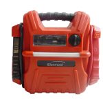
Linsheng – Car Starter: How To Start The Car Emergency?
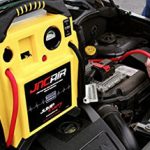
linsheng stated that the factories that generally do emergency power supply for automobiles do not have core product technology. The battery cells are used as a process of assembly and integration, so such products are not competitive in the market. At present, the sales of automobile emergency start power products are increasing linearly at a rate of 30% per month, and the market is steadily rising. After the weather gradually cooled down in October of the second half of the year, the car emergency starter products will continue to usher in its peak season.
1. Input voltage VIN range: The transient range of the 12V battery voltage determines the input voltage range of the power conversion IC.
A typical car battery voltage range is 9V to 16V. When the engine is off, the nominal voltage of the car battery is 12V. When the engine is running, the battery voltage is about 14.4V. However, under different conditions, the transient voltage may also reach ±100V. The ISO7637-1 industry standard defines the range of voltage fluctuations in automotive batteries. In addition to ISO7637-1, there are some battery operating ranges and environments defined for gas engines. Most new specifications are proposed by different OEMs and do not necessarily follow industry standards. However, any new standard that requires vehicle safety requires overvoltage and undervoltage and anti-backlash protection.
2, heat dissipation considerations: heat dissipation needs to be designed according to the lowest efficiency of DC-DC converter
In applications where air circulation is poor or there is no air circulation, if the ambient temperature is high (> 30 ° C), there is a heat source (> 1 W) in the enclosure and the equipment will rapidly heat up (> 85 ° C). For example, most audio amplifiers need to be mounted on a heat sink and need to provide good airflow conditions to dissipate heat. In addition, the PCB material and certain copper-clad areas help to improve heat transfer efficiency for optimum heat dissipation. If the heat sink is not used, the heat dissipation capability of the exposed pad on the package is limited to 2W to 3W (85°C). As the ambient temperature increases, the heat dissipation capacity is significantly reduced.
When converting the battery voltage to a low voltage (eg 3.3V) output, the linear regulator will lose 75% of the input power with very low efficiency. In order to provide 1W of output power, 3W of power will be dissipated as heat. Limited by ambient temperature and case/junction thermal resistance, the maximum output power of 1W will be significantly reduced. For most high-voltage DC-DC converters, LDOs offer a high price/performance ratio when the output current is in the 150mA to 200mA range.
Converting the battery voltage to low voltage (for example: 3.3V), when the power reaches 3W, you need to choose the high-side switching converter, which can provide more than 30W output power. This is why automotive power supply manufacturers typically use switching power supply solutions to exclude traditional LDO-based architectures.
3. Static operating current (IQ) and shutdown current (ISD)
As the number of electronic control units (ECUs) in automobiles increases rapidly, the total current consumed from automotive batteries continues to increase. Some ECU units remain active even when the engine is off and the battery is exhausted. In order to ensure that the static operating current IQ is within the controllable range, most OEMs begin to limit the IQ of each ECU. For example, the EU’s request is: 100μA/ECU. Most EU automotive standards dictate that the ECU’s typical IQ is less than 100μA. Devices that are always active, such as CAN transceivers, real-time clocks, and microcontroller current losses are key considerations for ECU IQ, and power supply designs need to consider a minimum IQ budget.
4. Cost control: OEM’s compromise between cost and specification is an important factor affecting the power supply bill of materials.
For products that are produced in large quantities, cost is an important factor to consider in the design. PCB type, heat dissipation capability, allowable package selection, and other design constraints are actually limited by the budget of a particular project. For example, with 4-layer FR4 and single-layer CM3, the heat dissipation capability of the PCB can vary greatly.
The project budget also leads to another constraint that users can accept higher cost ECUs, but does not spend time and money on retrofitting traditional power supply designs. For some new, costly development platforms, designers simply perform some simple retouching of unoptimized traditional power supply designs.
5, location / layout: PCB and component layout in power supply design will limit the overall performance of the power supply
Structural design, board layout, noise sensitivity, multilayer board interconnect issues, and other layout limitations can limit the design of high-chip integrated power supplies. The use of point-of-load power to generate all the necessary power supplies can also result in high costs, and it is not ideal to have many components on a single chip. Power supply designers need to balance overall system performance, mechanical constraints, and cost based on specific project needs.
6, electromagnetic radiation
The electric field that changes with time produces electromagnetic radiation. The intensity of the radiation depends on the frequency and amplitude of the field. The electromagnetic interference generated by one working circuit directly affects the other circuit. For example, interference from radio channels can cause airbag malfunctions. To avoid these negative effects, OEMs have set maximum electromagnetic radiation limits for ECU units.
In order to keep electromagnetic radiation (EMI) within a controlled range, the type of DC-DC converter, topology, peripheral component selection, board layout and shielding are all important. After years of accumulation, power IC designers have developed various techniques to limit EMI. External clock synchronization, operating frequency higher than the AM modulation band, built-in MOSFET, soft switching technology, and spread spectrum technology are all EMI suppression solutions that have been launched in recent years.
https://www.linsheng.com
